ESP32S31.14寸TFT Arduino
硬件设置
您需要准备以下内容:
1 个ESP32S3 1.14 TFT
1 台电脑
1 根 USB Type-C数据线
Tips
有些USB线只能供电,不能传输数据。如果您没有 USB 线或者不知道您的 USB 线是否可以传输数据,可以购买Type-c数据线
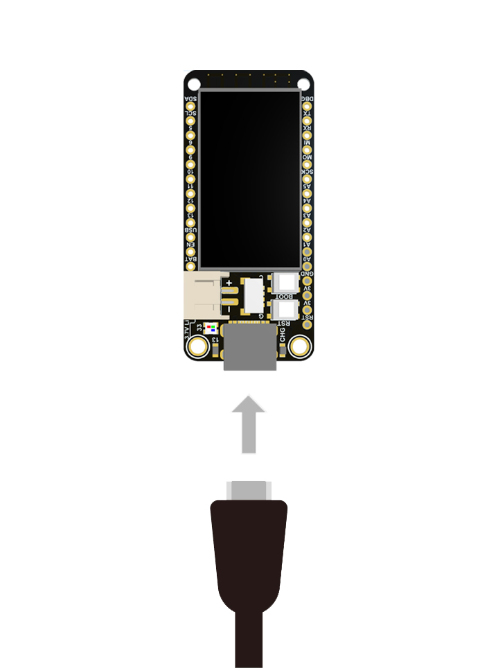
- 步骤 1.通过USB Type-C数据线将 ESP32S3 1.14 TFT连接到计算机(上电的时候需要安装BOOT)
软件设置
- 步骤1.根据您的操作系统下载并安装最新版本的Arduino IDE

如果下载缓慢可以在国内Arduino社区下载ArduinoIDE下载地址
步骤 2.启动 Arduino 应用程序
步骤 3.将 ESP32 板包添加到 Arduino IDE
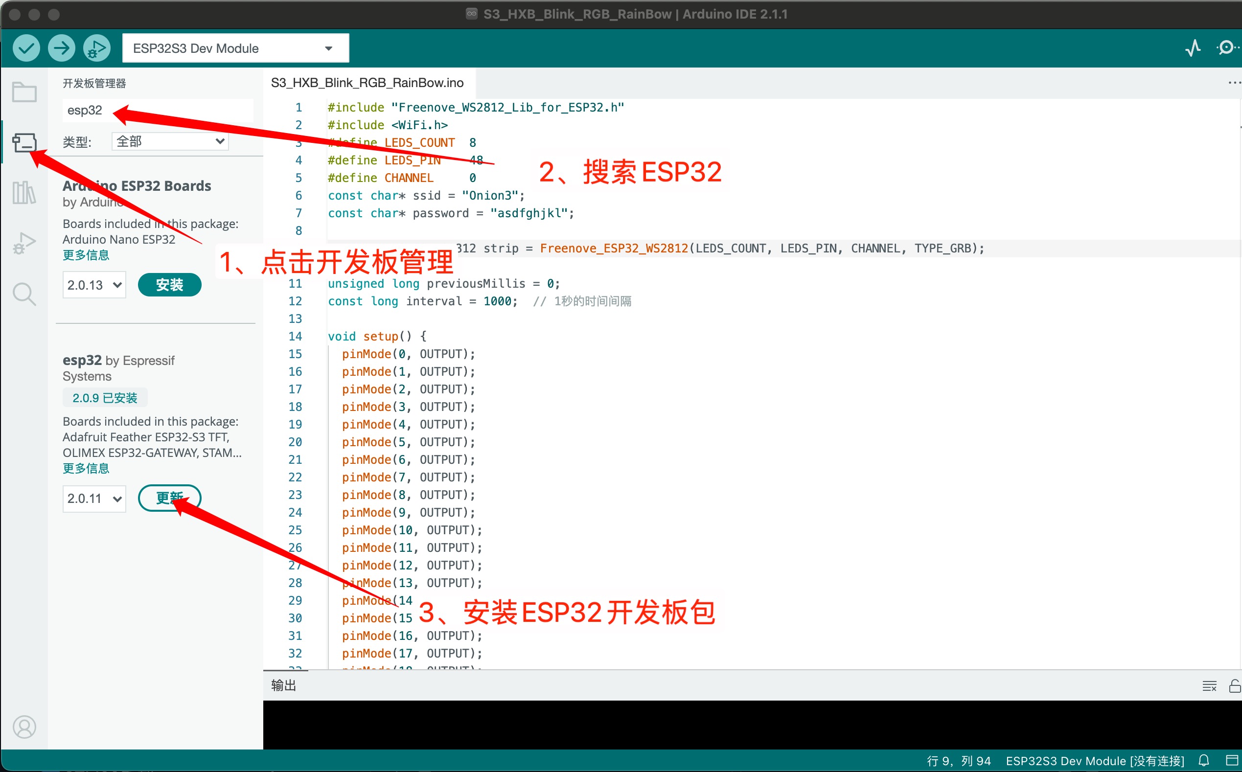
离线安装ESP32方法
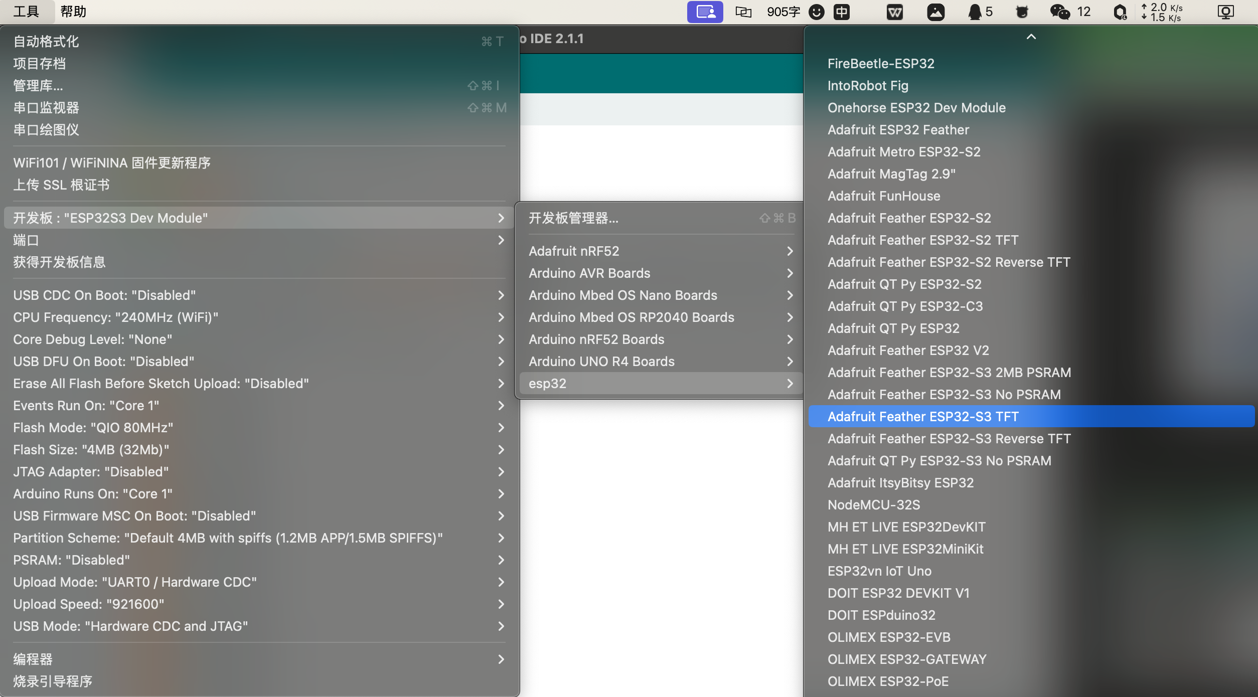
导航到工具 > 开发板 > ESP32 Arduino并选择“ Adafruit Feather ESP32-S3 TFT ”。板的列表有点长,你需要滚动到底部才能到达它。
导航到“工具”>“端口”,然后选择所连接的 ESP32S3 1.14 TFT 的串口名称。这可能是 COM3 或更高版本(COM1和COM2通常保留用于硬件串行端口)。
Warning
将代码从 Arduino IDE 上传到 ESP32-S3 后,请务必按下重置按钮!否则程序不运行
Warning
ESP32-S2/S3 引导加载程序不支持 Windows 7 或 8 的 USB 串行支持。(参考https://github.com/espressif/arduino-esp32/issues/5994)。 请更新到 espressif 支持的版本WIn 10!或者,您可以尝试这个社区制作的 Windows 7 驱动程序 ( https://github.com/kutukvpavel/Esp32-Win7-VCP-drivers )
端口识别
ESP32S3内置USB,但是Arduino对ESP32S3系列支持不太友好,直接插入到电脑,你可能会无法看到COM口,你可以通过手动进入引导加载模式,该引导加载程序位于ROM中,是不可修改的,因此你可以随时使用此方法进入引导加载程序。在Arduino上传代码后,必须要按一下RST按键才能运行程序。
Tips
- 1、通过按住Boot按键上电,来进入引导加载模式。(就是没插USB之前,一直按住BOOT按键,当插入之后,松开BOOT按键)
- 2、当已插数据线的时候,只需要长按Boot,然后按一下RST按键,就可以进入引导加载模式。(一直按住Boot,当按下RST按键松开之后,Boot按键就可以松开)
LED
步骤1.将以下代码复制到Arduino IDE
// define led according to pin diagram
int led = 13;

void setup() {
  // initialize digital pin led as an output
  pinMode(led, OUTPUT);
}

void loop() {
  digitalWrite(led, HIGH);   // turn the LED on
  delay(1000);               // wait for a second
  digitalWrite(led, LOW);    // turn the LED off
  delay(1000);               // wait for a second
}
上传后,您将看到板子上的红色LED 闪烁,每次闪烁之间有 1 秒的延迟。
RGB
RGB库推荐使用 Adafruit_NeoPixe 库。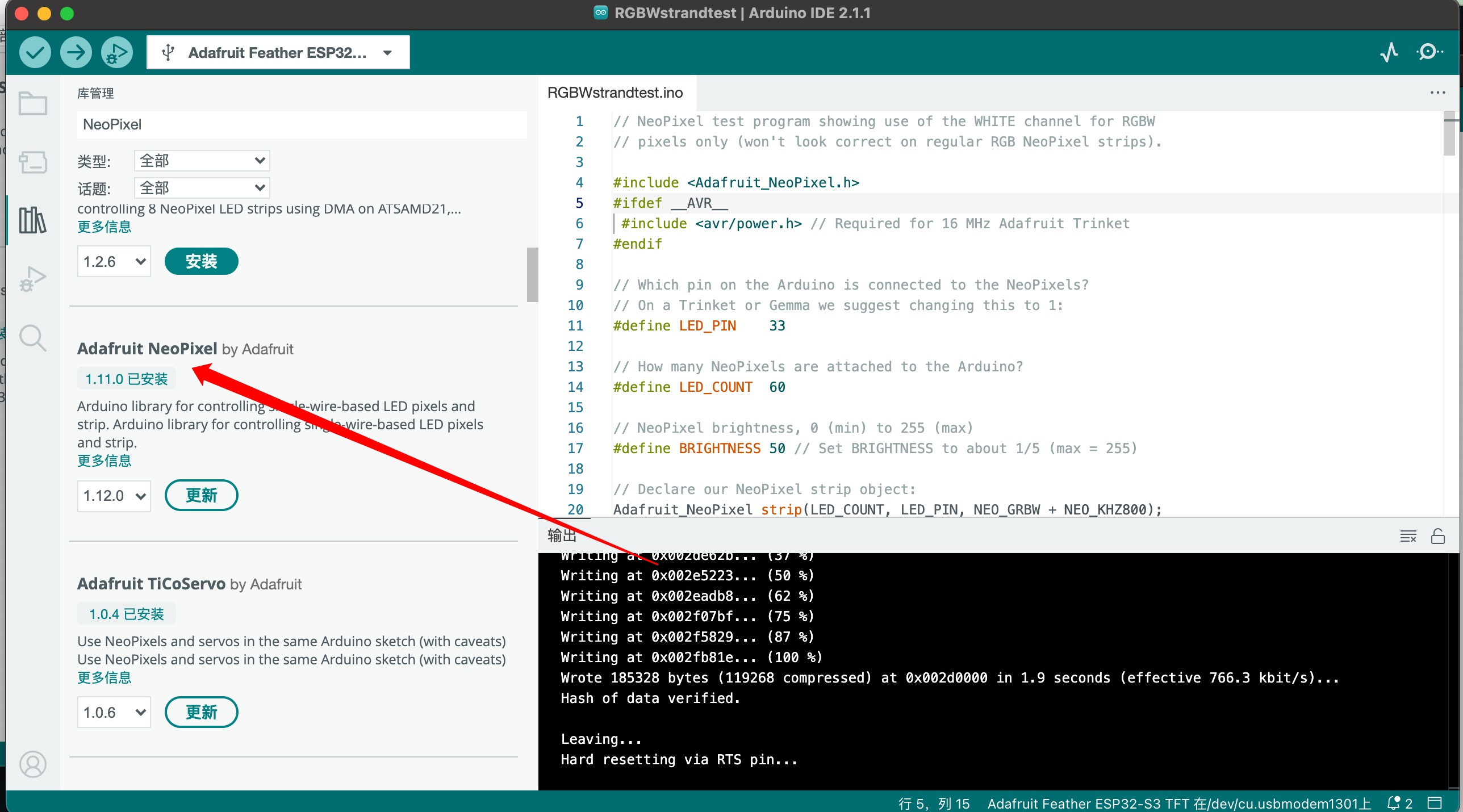
示例代码
// NeoPixel test program showing use of the WHITE channel for RGBW
// pixels only (won't look correct on regular RGB NeoPixel strips).

#include <Adafruit_NeoPixel.h>
#ifdef __AVR__
 #include <avr/power.h> // Required for 16 MHz Adafruit Trinket
#endif

// Which pin on the Arduino is connected to the NeoPixels?
// On a Trinket or Gemma we suggest changing this to 1:
#define LED_PIN    33

// How many NeoPixels are attached to the Arduino?
#define LED_COUNT  60

// NeoPixel brightness, 0 (min) to 255 (max)
#define BRIGHTNESS 50 // Set BRIGHTNESS to about 1/5 (max = 255)

// Declare our NeoPixel strip object:
Adafruit_NeoPixel strip(LED_COUNT, LED_PIN, NEO_GRBW + NEO_KHZ800);
// Argument 1 = Number of pixels in NeoPixel strip
// Argument 2 = Arduino pin number (most are valid)
// Argument 3 = Pixel type flags, add together as needed:
//   NEO_KHZ800  800 KHz bitstream (most NeoPixel products w/WS2812 LEDs)
//   NEO_KHZ400  400 KHz (classic 'v1' (not v2) FLORA pixels, WS2811 drivers)
//   NEO_GRB     Pixels are wired for GRB bitstream (most NeoPixel products)
//   NEO_RGB     Pixels are wired for RGB bitstream (v1 FLORA pixels, not v2)
//   NEO_RGBW    Pixels are wired for RGBW bitstream (NeoPixel RGBW products)

void setup() {
  // These lines are specifically to support the Adafruit Trinket 5V 16 MHz.
  // Any other board, you can remove this part (but no harm leaving it):
#if defined(__AVR_ATtiny85__) && (F_CPU == 16000000)
  clock_prescale_set(clock_div_1);
#endif
  // END of Trinket-specific code.

  strip.begin();           // INITIALIZE NeoPixel strip object (REQUIRED)
  strip.show();            // Turn OFF all pixels ASAP
  strip.setBrightness(BRIGHTNESS);
}

void loop() {
  // Fill along the length of the strip in various colors...
  colorWipe(strip.Color(255,   0,   0)     , 50); // Red
  colorWipe(strip.Color(  0, 255,   0)     , 50); // Green
  colorWipe(strip.Color(  0,   0, 255)     , 50); // Blue
  colorWipe(strip.Color(  0,   0,   0, 255), 50); // True white (not RGB white)

  whiteOverRainbow(75, 5);

  pulseWhite(5);

  rainbowFade2White(3, 3, 1);
}

// Fill strip pixels one after another with a color. Strip is NOT cleared
// first; anything there will be covered pixel by pixel. Pass in color
// (as a single 'packed' 32-bit value, which you can get by calling
// strip.Color(red, green, blue) as shown in the loop() function above),
// and a delay time (in milliseconds) between pixels.
void colorWipe(uint32_t color, int wait) {
  for(int i=0; i<strip.numPixels(); i++) { // For each pixel in strip...
    strip.setPixelColor(i, color);         //  Set pixel's color (in RAM)
    strip.show();                          //  Update strip to match
    delay(wait);                           //  Pause for a moment
  }
}

void whiteOverRainbow(int whiteSpeed, int whiteLength) {

  if(whiteLength >= strip.numPixels()) whiteLength = strip.numPixels() - 1;

  int      head          = whiteLength - 1;
  int      tail          = 0;
  int      loops         = 3;
  int      loopNum       = 0;
  uint32_t lastTime      = millis();
  uint32_t firstPixelHue = 0;

  for(;;) { // Repeat forever (or until a 'break' or 'return')
    for(int i=0; i<strip.numPixels(); i++) {  // For each pixel in strip...
      if(((i >= tail) && (i <= head)) ||      //  If between head & tail...
         ((tail > head) && ((i >= tail) || (i <= head)))) {
        strip.setPixelColor(i, strip.Color(0, 0, 0, 255)); // Set white
      } else {                                             // else set rainbow
        int pixelHue = firstPixelHue + (i * 65536L / strip.numPixels());
        strip.setPixelColor(i, strip.gamma32(strip.ColorHSV(pixelHue)));
      }
    }

    strip.show(); // Update strip with new contents
    // There's no delay here, it just runs full-tilt until the timer and
    // counter combination below runs out.

    firstPixelHue += 40; // Advance just a little along the color wheel

    if((millis() - lastTime) > whiteSpeed) { // Time to update head/tail?
      if(++head >= strip.numPixels()) {      // Advance head, wrap around
        head = 0;
        if(++loopNum >= loops) return;
      }
      if(++tail >= strip.numPixels()) {      // Advance tail, wrap around
        tail = 0;
      }
      lastTime = millis();                   // Save time of last movement
    }
  }
}

void pulseWhite(uint8_t wait) {
  for(int j=0; j<256; j++) { // Ramp up from 0 to 255
    // Fill entire strip with white at gamma-corrected brightness level 'j':
    strip.fill(strip.Color(0, 0, 0, strip.gamma8(j)));
    strip.show();
    delay(wait);
  }

  for(int j=255; j>=0; j--) { // Ramp down from 255 to 0
    strip.fill(strip.Color(0, 0, 0, strip.gamma8(j)));
    strip.show();
    delay(wait);
  }
}

void rainbowFade2White(int wait, int rainbowLoops, int whiteLoops) {
  int fadeVal=0, fadeMax=100;

  // Hue of first pixel runs 'rainbowLoops' complete loops through the color
  // wheel. Color wheel has a range of 65536 but it's OK if we roll over, so
  // just count from 0 to rainbowLoops*65536, using steps of 256 so we
  // advance around the wheel at a decent clip.
  for(uint32_t firstPixelHue = 0; firstPixelHue < rainbowLoops*65536;
    firstPixelHue += 256) {

    for(int i=0; i<strip.numPixels(); i++) { // For each pixel in strip...

      // Offset pixel hue by an amount to make one full revolution of the
      // color wheel (range of 65536) along the length of the strip
      // (strip.numPixels() steps):
      uint32_t pixelHue = firstPixelHue + (i * 65536L / strip.numPixels());

      // strip.ColorHSV() can take 1 or 3 arguments: a hue (0 to 65535) or
      // optionally add saturation and value (brightness) (each 0 to 255).
      // Here we're using just the three-argument variant, though the
      // second value (saturation) is a constant 255.
      strip.setPixelColor(i, strip.gamma32(strip.ColorHSV(pixelHue, 255,
        255 * fadeVal / fadeMax)));
    }

    strip.show();
    delay(wait);

    if(firstPixelHue < 65536) {                              // First loop,
      if(fadeVal < fadeMax) fadeVal++;                       // fade in
    } else if(firstPixelHue >= ((rainbowLoops-1) * 65536)) { // Last loop,
      if(fadeVal > 0) fadeVal--;                             // fade out
    } else {
      fadeVal = fadeMax; // Interim loop, make sure fade is at max
    }
  }

  for(int k=0; k<whiteLoops; k++) {
    for(int j=0; j<256; j++) { // Ramp up 0 to 255
      // Fill entire strip with white at gamma-corrected brightness level 'j':
      strip.fill(strip.Color(0, 0, 0, strip.gamma8(j)));
      strip.show();
    }
    delay(1000); // Pause 1 second
    for(int j=255; j>=0; j--) { // Ramp down 255 to 0
      strip.fill(strip.Color(0, 0, 0, strip.gamma8(j)));
      strip.show();
    }
  }

  delay(500); // Pause 1/2 second
}
I2C扫描
许多传感器、显示器和设备都可以通过 I2C 连接。I2C 是一种 2 线“总线”,允许多个设备全部连接在一组引脚上,因此接线非常方便!
使用开发板时,您可能需要连接 I2C 设备,第一次可能会有点棘手。调试 I2C 的最佳方法是检查接线,然后执行 I2C 扫描
Tips
在库管理中搜索并安装TestBed。
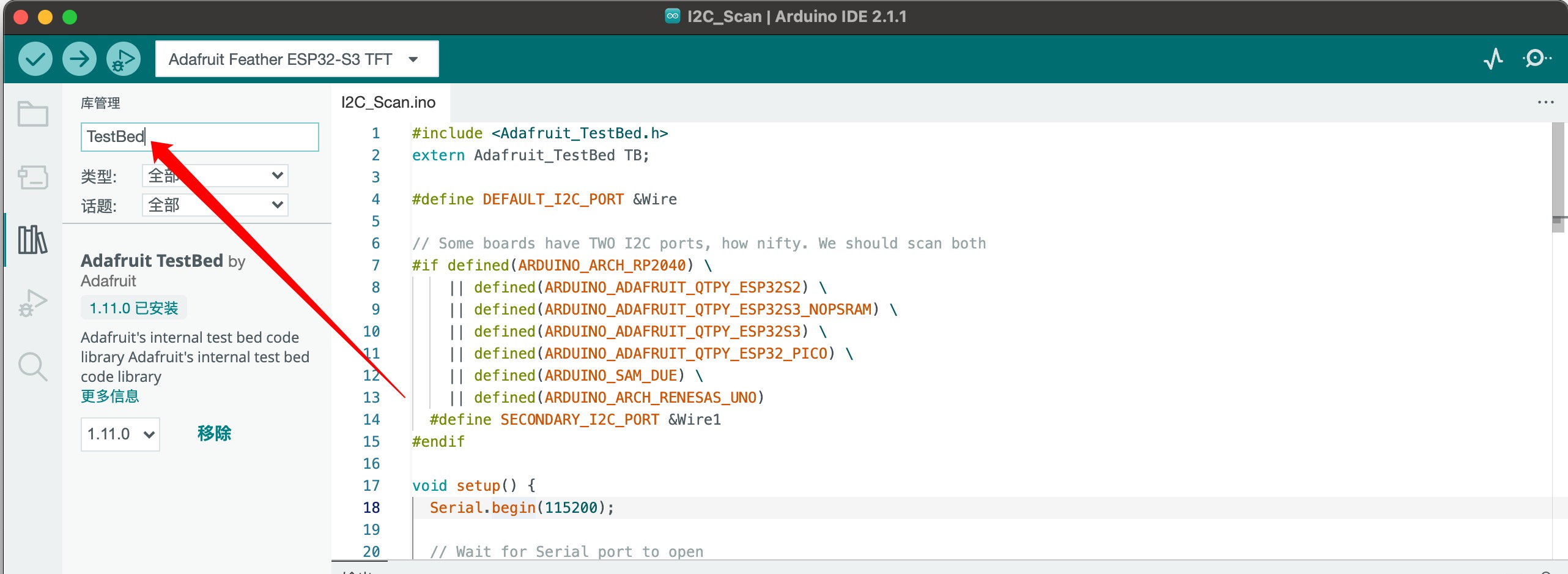
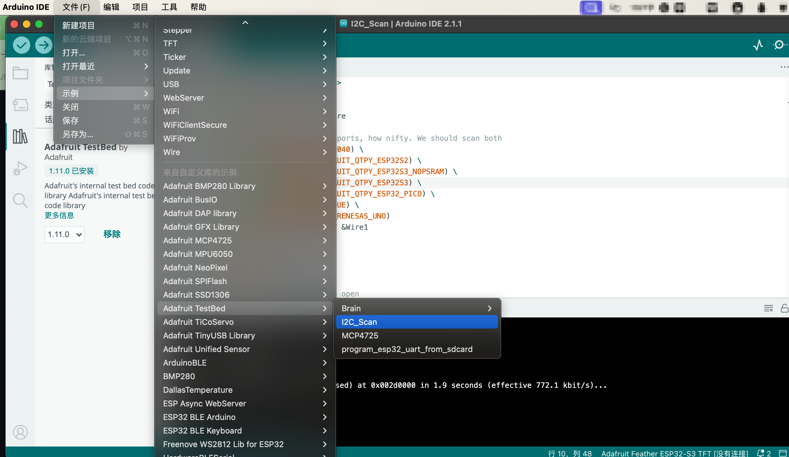
安装完成后,可以复制一下代码,进行I2C扫描,或者直接在安装的库的示例中选择,如下图所示。
示例代码
#include <Adafruit_TestBed.h>
extern Adafruit_TestBed TB;

#define DEFAULT_I2C_PORT &Wire

// Some boards have TWO I2C ports, how nifty. We should scan both
#if defined(ARDUINO_ARCH_RP2040) \
    || defined(ARDUINO_ADAFRUIT_QTPY_ESP32S2) \
    || defined(ARDUINO_ADAFRUIT_QTPY_ESP32S3_NOPSRAM) \
    || defined(ARDUINO_ADAFRUIT_QTPY_ESP32S3) \
    || defined(ARDUINO_ADAFRUIT_QTPY_ESP32_PICO) \
    || defined(ARDUINO_SAM_DUE) \
    || defined(ARDUINO_ARCH_RENESAS_UNO)
  #define SECONDARY_I2C_PORT &Wire1
#endif

void setup() {
  Serial.begin(115200);

  // Wait for Serial port to open
  while (!Serial) {
    delay(10);
  }
  delay(500);
  Serial.println("WMNologo I2C Scanner");

#if defined(ARDUINO_ADAFRUIT_QTPY_ESP32S2) || \
    defined(ARDUINO_ADAFRUIT_QTPY_ESP32S3_NOPSRAM) || \
    defined(ARDUINO_ADAFRUIT_QTPY_ESP32S3) || \
    defined(ARDUINO_ADAFRUIT_QTPY_ESP32_PICO)
  // ESP32 is kinda odd in that secondary ports must be manually
  // assigned their pins with setPins()!
  Wire1.setPins(SDA1, SCL1);
#endif

#if defined(ARDUINO_ADAFRUIT_FEATHER_ESP32S2)
  // turn on the I2C power by setting pin to opposite of 'rest state'
  pinMode(PIN_I2C_POWER, INPUT);
  delay(1);
  bool polarity = digitalRead(PIN_I2C_POWER);
  pinMode(PIN_I2C_POWER, OUTPUT);
  digitalWrite(PIN_I2C_POWER, !polarity);
#endif

#if defined(ARDUINO_ADAFRUIT_FEATHER_ESP32S2_TFT)
  pinMode(TFT_I2C_POWER, OUTPUT);
  digitalWrite(TFT_I2C_POWER, HIGH);
#endif

#if defined(ARDUINO_ADAFRUIT_FEATHER_ESP32S2_REVTFT)
  pinMode(TFT_I2C_POWER, OUTPUT);
  digitalWrite(TFT_I2C_POWER, HIGH);
#endif

#if defined(ADAFRUIT_FEATHER_ESP32_V2)
  // Turn on the I2C power by pulling pin HIGH.
  pinMode(NEOPIXEL_I2C_POWER, OUTPUT);
  digitalWrite(NEOPIXEL_I2C_POWER, HIGH);
#endif
}

void loop() {
  Serial.println("");
  Serial.println("");

  Serial.print("Default port (Wire) ");
  TB.theWire = DEFAULT_I2C_PORT;
  TB.printI2CBusScan();

#if defined(SECONDARY_I2C_PORT)
  Serial.print("Secondary port (Wire1) ");
  TB.theWire = SECONDARY_I2C_PORT;
  TB.printI2CBusScan();
#endif

  delay(3000); // wait 3 seconds
}
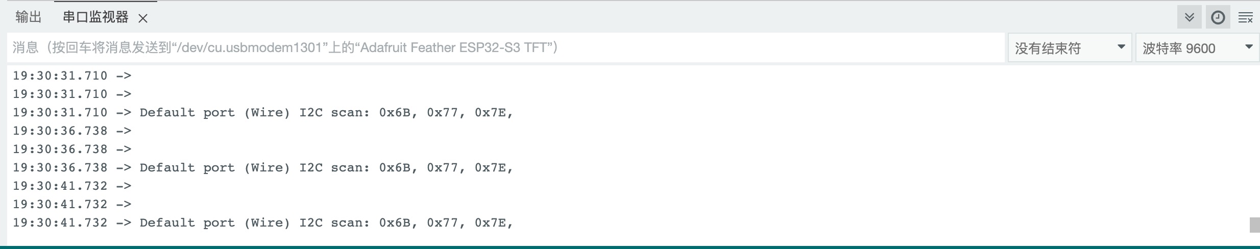
Tips
可以看到扫描出三个I2C地址,其中0X6B是QMI8658的I2C地址,0X77是BMP280的I2C地址。