ESP32S3SuperMini 引脚使用
大约 2 分钟
ESP32S3SuperMini 接口丰富。有11 个数字 I/O可用作PWM 引脚,4 个模拟输入可用作ADC 引脚。它支持UART、I2C、SPI和I2S等四种串行通信接口。该文章将有助于了解这些接口并在您的下一个项目中实现它们!
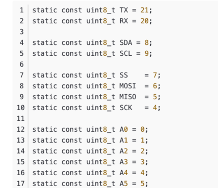
关于引脚A0A5,GPIO0GPIO10(010)、以及D开头的,在这里讲解一下,默认主板只有GPIO开头的也就是010、20、21,出现A0~A5引脚是映射的问题,是为了方便告诉用户这个引脚的功能是模拟引脚还是数字引脚。在Arduino选择开发板类型的时候选择的是 ESP32S3 Dev Module ,就可以引用他的引脚映射。引脚映射图如下。
Digital 数字引脚
将一下代码上传到主板,板载LED将每隔一秒亮灭。
// define led according to pin diagram
int led = 8;

void setup() {
  // initialize digital pin led as an output
  pinMode(led, OUTPUT);
}

void loop() {
  digitalWrite(led, HIGH);   // turn the LED on
  delay(1000);               // wait for a second
  digitalWrite(led, LOW);    // turn the LED off
  delay(1000);               // wait for a second
}
Digital PWM
上传以下代码即可看到 板载LED 逐渐变暗。
int ledPin = 8;    // LED connected to digital pin 10

void setup() {
  // declaring LED pin as output
  pinMode(ledPin, OUTPUT);
}

void loop() {
  // fade in from min to max in increments of 5 points:
  for (int fadeValue = 0 ; fadeValue <= 255; fadeValue += 5) {
    // sets the value (range from 0 to 255):
    analogWrite(ledPin, fadeValue);
    // wait for 30 milliseconds to see the dimming effect
    delay(30);
  }

  // fade out from max to min in increments of 5 points:
  for (int fadeValue = 255 ; fadeValue >= 0; fadeValue -= 5) {
    // sets the value (range from 0 to 255):
    analogWrite(ledPin, fadeValue);
    // wait for 30 milliseconds to see the dimming effect
    delay(30);
  }
}
Analog 模拟引脚
将电位计连接到引脚 A5,然后上传以下代码,通过旋转电位器旋钮来控制LED的闪烁间隔。
const int sensorPin = A5;
const int ledPin =  8;

void setup() {
  pinMode(sensorPin, INPUT);  // declare the sensorPin as an INPUT
  pinMode(ledPin, OUTPUT);   // declare the ledPin as an OUTPUT
}

void loop() {
  // read the value from the sensor:
  int sensorValue = analogRead(sensorPin);
  // turn the ledPin on
  digitalWrite(ledPin, HIGH);
  // stop the program for <sensorValue> milliseconds:
  delay(sensorValue);
  // turn the ledPin off:
  digitalWrite(ledPin, LOW);
  // stop the program for for <sensorValue> milliseconds:
  delay(sensorValue);
}
Serial 串口
硬串口
板子上有两个硬件串口
- USB串口
- UART串口
默认情况下,USB 串行处于启用状态,这意味着您可以通过 USB Type-C 将开发板连接到 PC,并在 Arduino IDE 上打开串行监视器以查看通过串行发送的数据。
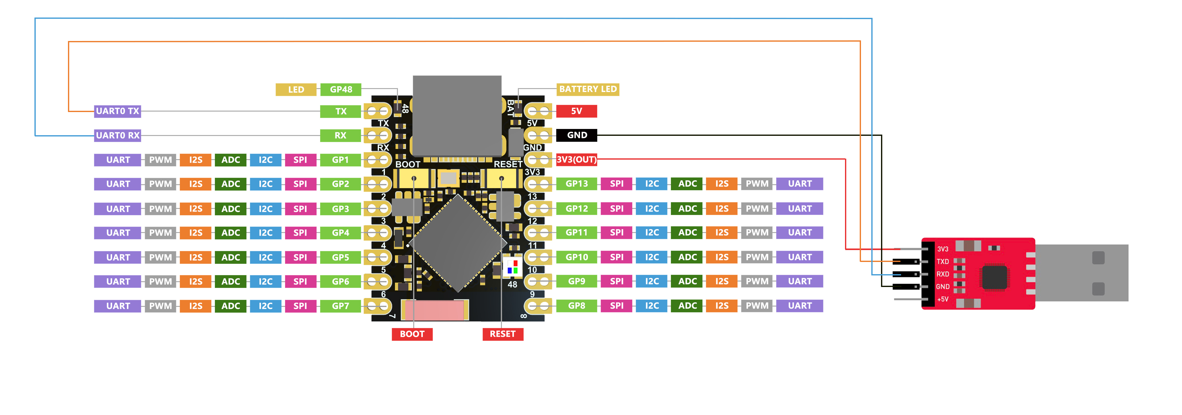
但是,如果您想使用 UART 作为串口,则需要使用 USB 串行适配器将引脚 TX 连接为 TX 引脚,将引脚 RX 连接为 RX 引脚。
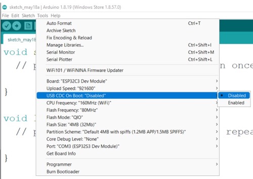
另外,您需要从 Arduino IDE 将USB CDC On Boot设置为禁用。
软串口
如果想使用更多串口,需要使用SoftwareSerial库来创建软串口。(可以自行百度)